FAQ : IPv6 : What is IPv6?
What is IPv6?Internet Protocol Version 6 : IPv6 - The Next Generation
Original Authors: Adrian M. Estala and Alain Leroy. IPv6 DefinedThe Internet Protocol version 6 effort is dynamic and is being driven by worldwide sites currently implementing and testing its functionality. Multiple Request for Comments (RFC) and Internet Drafts have been written to support those interested in joining the testing effort. The information presented in this chapter provides a thorough platform from which further investigations can begin. The first step to understanding IPv6 is to appreciate the forces that have driven the need for a new internet protocol. Thus, the chapter begins by describing the market and networking needs that have motivated the design of IPv6. In defining IPv6, the chapter focuses on the changes and improvements from IPv4. The description of the IPv6 Header focuses on the new Extension Header. Following, is a discussion of the increased address size. The new 128 bit address size affords new addressing types and new addressing functions. Finally, the chapter closes with the descriptions of IPv6 improvements in routing and security. Motivation For New ProtocolInternet Protocol version 6 (IPv6) is the next generation of internet protocol, the current version is IPv4. The current exponential growth of the internet is the primary driver for the need of a new protocol. IPv4 addressing and routing limitations continue to be stretched to their limits, while internet growth rates are progressively increasing. Furthermore, IPv4 lacks the proper security and authentication techniques that are necessary for today's market needs. IPv6 has been developed to facilitate emerging internet growth rates by meeting the needs of tomorrow's users. Built on the foundations of IPv4, IPv6 will continue to connect the world. Many essential elements were considered in the design of IPv6. One vital aspect was forecasting the needs of future markets. Future internet markets will rely on security, efficiency, and mobility. Another key issue that is just as imperative to the success of IPv6 is the internet's transition from IPv4. The transition involves incremental steps that do not hinder existing networks. IPv6 has been developed to work with existing network protocols. Whether by creating tunnels to carry IPv6 packets or by creating IPv6 tunnels to carry other protocol packets, IPv6 will strengthen the current internet network without requiring any obstructive changes. As the advantages of IPv6 become readily more apparent, users can progressively make the change into IPv6 naturally and voluntarily. Meanwhile, new IPv6 applications and documentation will continue to propitiate the transition process. Three key points will ensure that the next generation of the Internet Protocol evolves successfully:
What is IPv6?IPv6 supports most of the same functions and applications that were supported in IPv4. Those functions that were not successful in IPv4 were either not included or improved in IPv6. The changes in IPv6 include
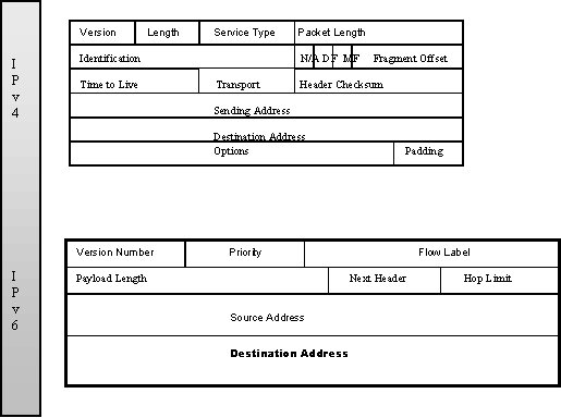
IPv6 HeaderThe IPv6 Header has greatly evolved from its IPv4 predecessor. The IPv6 Header is larger but takes up a lesser percentage of the overall header space. Several fields such as the Options Field and Header Checksum have been removed and replaced with improved functions in the IPv6 Extension Header. The IPv6 Header was designed to facilitate routing efficiency. IPv6 Header FormatThe IPv4 Header was inherently inefficient as routing required the analysis of each of the IPv4 Header Fields. IPv6 introduces the Extension Header which is described by a value in the IPv6 Next Header Field. Routers can view the Next Header value and then independently and quickly decide if the Extension Header holds useful information. The Extension Headers carry much of the information that contributed to the large size of the IPv4 Header. Consequently, the IPv6 Header is relatively smaller. The Extension Header is further described in the next section.
The description of the IPv6 Header Fields are described in the table below.
IPv6 Extension HeaderIPv6 options are placed in separate Extension Headers to facilitate routing and to provide a practical means to implement additional options. The Extension Headers are placed between the Transport Layer Header and the IPv6 Header. Several types of Extension Headers are defined for IPv6, a value in the Next Header Field identifies the type of Extension Header that follows. Every header contains its own Next Header Field to identify subsequent headers. The Extension Headers are placed in order so that a router can stop reading the Next Header field once it reaches the last value or Extension Header that may pertain to it. In this fashion, all of the extension options do not have to be processed by each router that the packet traverses along its way to the destination. In fact, many IPv6 Extension Headers are not processed until they arrive at the destination. The variable length Extension Header may extend beyond the 40 byte limit in IPv4 options. This flexibility allows for the practical use of security options in the Extension Headers. For example, the Authentication Extension Header may contain Algorithmic information to assure the secure IPv6 packet transfer. Many options have already been defined for use in IPv6 Extension Headers. These options are grouped in integer multiples of 8 octets. This grouping format is used to retain alignment for the Transport Protocol Headers that follow. Some of the currently assigned options and the assigned values that identify them in the Next Header Field are:
Routing HeadersRouting Extension Headers are used by the source to control the routing of a packet. In this fashion, the Routing header may explicitly dictate the route from the source to the destination. The IPv6 address of each of the nodes along the path are included, and the destination then uses the reverse path for communication as well. This topic is further discussed in the IPv6 Routing section. Fragmentation HeadersAlthough the IPv6 effort aims to prevent subsequent fragmentation, the Fragmentation Header allows fragmented packets to traverse the IPv6 network. Authentication HeadersThe Authentication Header uses an algorithm to ensure that the IPv6 packet has not been altered along its path. The header also ensures that the IPv6 packet has arrived from the source listed in the IP Header. The Authentication Header is further described in the IPv6 Security Issues section. Hop-by-Hop HeaderIPv6 implements an efficient method to alert routers of a packet that requires special processing. Packets that do not contain the IPv6 Hop-by-Hop Option Header are not fully processed by each router, instead they are allowed to quickly continue on their way to their destination. This method allows routers to quickly identify and fully process packets that require special route handling. Routers that recognize this Option Header examine the packets accordingly, routers that do not recognize this option ignore it. The process of IPv6 Hop-by-Hop Option Headers is fully described in the Internet Draft dated February 1998, and titled "IPv6 Router Alert Option." ICMPv6 HeaderInternet Control Message Protocol version 6 defines IPv6 node to node messaging techniques. Nodes use ICMPv6 to communicate errors and to perform diagnostic functions. ICMPv6 has many changes from ICMPv4. ICMPv6 messages always follow an IPv6 Header and any IPv6 Extension Headers that may exist. A Next Header Field value of 58 identifies that the next header is an ICMPv6 Header. This header format is shown in Figure 1.2.
Figure 1.2: ICMPv6 Header Format The Type field is 8 bits long. This field defines the ICMPv6 Message as either an error message or an informational message. A zero in the high order bit of this field indicates that the message is an error message. A one in the high order bit indicates that the message is an informational message. In this fashion, type field decimal values from 0-127 are error messages, and values from 128-255 are informational messages. The Internet Draft titled "Internet control Message Protocol (ICMPv6) for the Internet Protocol Version 6 (IPv6) Specification" discusses the message formats for the following ICMPv6 messages:
The 8 bit Code Field depends on the message type. For an Error Message, the Code Field might give more specific information about the type of error encountered. The 16 bit Checksum is used to detect errors inside of the ICMPv6 message. The Message Field may be used to contain part of the packet that an Error Message relates to. Note, the ICMPv6 packet may not exceed 576 octets. For Informational Messages the Message Field contains three separate fields; the Identifier Field, the Sequence Number Field, and the Data Field. The Identifier and Sequence Fields are used to invoke Echo Requests or match Echo Replies to their corresponding Echo Requests. The Data Field carries the information from the reply or arbitrary data for an Echo Request. IPv6 AddressingInternet Protocol version 6 addresses refer to interfaces. A node with two network cards has two interfaces. In IPv6 the node may have several addresses for each interface to facilitate routing. The functionality of IPv6 allows the administrator to define a node's interface's with multiple addresses and types of addresses. A node may be identified by any of the Unicast Address types that are assigned to any of its interfaces. The Unicast Address is further described later in this section. In this manner, any given interface may have a specific Link-Local Address for local communication, a Global Address for exterior communications, and an Anycast Address for special routing paths. Still, an administrator may also assign Multicast Addresses for ICMPv6 messages or to specify routing to certain groups. The broadcast address is not defined in IPv6, Multicast Addresses perform the functions of the Broadcast Address. By assigning different types of addresses, the network administrator has greater control over routing and congestion problems. 128 bit Address FieldThe IPv6 address is four times the size of the IPv4 address. This allows for 3.40 x 1038 addresses. It would be impossible to construct an internet that could take advantage of all of the address space, yet, even the lowest estimates predict over 1.99 x 1033 addresses. The world is expected to have eleven billion people in the year 2150. With proper management, IPv6 could enjoy a longer life than IPv4. Most likely, future needs for a new protocol will be driven by new technological advancements and not by a lack of address space. Text Representation of AddressesThe preferred form to represent an IPv6 address is X:X:X:X:X:X:X:X, where each X is a hexadecimal value representing two bytes or 16 bits. The leading zeroes in an individual field may be omitted. Groups of zeroes across multiple all zero fields can be represented by ::, for example:
A special format is used to show IPv4 in IPv6 address types. This format uses both the IPv6 colon and the IPv4 period to distinguish the different sections of the address, for example:
The IPv6 address that identifies the local machine is made up an IPv6 prefix and the IPv6 Interface Identifier. The IPv6 prefix is the first part of the address, its length is variable. The prefix for the Link Local Address is FE80, and the prefix for a Global Address may be up to 64 bits long. Thus, in order to explicitly identify which part of the address is the prefix, one should use an alternate format. This format uses a forward slash followed by the prefix length in bits. The forward slash and number is appended to the address. The example below illustrates a 64 bit prefix: IPv6 Address: 2001:db8:2000:240:290:27ff:fe24:c19f/64 64bit prefix: 2001:db8:2000:240::/64 IPv6 Address TypesThere are three main types of IPv6 addresses, Unicast, Anycast, and Multicast. The address type is identified by the leading bits in the address, called the Format Prefix field. The Format Prefix is a variable length field. Table 1 shows the Format Prefix values that have been assigned.
Table 1 Current IPv6 Address Type Allocation Every address listed in the table is a Unicast Address except for the last entry which is a Multicast Address. The Anycast Address is made by assigning a Unicast Address to multiple interfaces. Once the Anycast Address interfaces are properly configured, the Anycast Address will always be routed to the closest routable interface matching that address. The remainder of the space is reserved for future use. The Internet Draft dated January 1998 and titled "IPv6 Addressing Architecture"provides the following information:
Unspecified AddressThe Unspecified Address is 0:0:0:0:0:0:0:0 . It should never be assigned to any interface. This address is used to specify the absence of an address, such as before the address has been properly configured. Loopback AddressThe Loopback Address is represented by ::1 It should not be assigned to an interface, but rather it is assigned to a virtual interface for loopback purposes. Unicast AddressThe Unicast Address identifies a single interface. The Unicast Address may be aggregated using a process that is similar to current IPv4 Class-less InterDomain Routing (CIDR) The many types of Unicast addresses include; neutral-interconnect addresses, NSAP addresses, IPX hierarchical addresses, site-local-use address, link-local-use address, and the IPv4 capable host address. The complexity of the Unicast Address format will vary depending on what amount of information the address should provide. For example, the Provider Based Unicast Address will provide much more information than a Link-Local Unicast Address. Inherently, the provider will require much more information to locate a host. Provider Based Unicast AddressThe Provider Based Unicast Address is used to define an interface for global use. The internet service provider gives the user its proper IPv6 prefix. Figure 1.4 illustrates the Provider Based Unicast Address Format.
Table 2 Provider Based Unicast Address Format The first 3 bits identify the address as a provider based Unicast Address. The Registry ID identifies the internet address registry which assigns provider identifiers (Provider ID) to internet service providers. The internet service providers then assign portions of the address space to subscribers. The Subscriber ID distinguishes among multiple subscribers attached to the internet service provider. The Subnet ID identifies a specific physical link. There can be multiple subnets on the same physical link. A Subnet ID can not span multiple physical links. The Interface ID identifies a single interface among the group of interfaces identified by the subnet prefix. Local-Use AddressesThe Local-Use Unicast Address is used within the subnet. This address can only be routed on the local subnet. This type of address allows groups to construct private intranets without having to request a global address prefix from the internet. Once the group is ready to connect to the internet, a global prefix can be allocated and appended to the Interface ID and the Subnet ID to form a unique Global Address. The Interface ID may be used by an interface to create many different typed of addresses. There are two types of Local-Use Addresses, the Link-Local and the Site-Local Address. Their names identify their use. The Link-Local Address is used on a single link, such as between a router and its directly connected hosts. All hosts are required to have at least one Link Local Address. Among other uses, these addresses may provide communications for autoconfiguration or for ICMPv6 Neighbor Discovery. This address type may also be used for communication on a link when no router is present. The Link Local Address is for on-link communication only, it cannot be forwarded by routers. As shown previously in Figure 1.3, the Link-Local Address Format Prefix is 10 bits long. Using the format shown in the Figure 1.6 with a 64 bit Interface ID, the complete link-local prefix for this example would be FE80. This prefix would represent the first 64 bits.
Table 4 Link Local Address Format Once an interface determines its Link Local Address, it can use ICMPv6 Router Solicitation to auto-configure its Global Address from a router on the same link. The process of autoconfiguration and the creation of the Interface ID is further described in the Autoconfiguration section. The Site-Local Address is used for communications in a given site. This address can be routed to other on-site subnets, within an intranet, without the need for a global prefix. Routers cannot forward Site-Local packets outside of the site. Table 5 illustrates the Site-Local Address Format, note that it is very similar to the Link-Local Address Format. In fact, if the Link-Local Address is thought of as having an all zero Subnet ID, the two formats are exactly alike except for the last bit in the Format Prefix. Appending the Subnet ID and the Interface ID to the Format Prefix produces the complete address. In this case, the site-local prefix would be FEC0. This prefix represents the first 48 bits.
Table 5 Site-Local Address Format IPv4-Compatible IPv6 AddressesIPv6 functionality allows nodes to dynamically tunnel IPv6 packets through an existing IPv4 infrastructure. Nodes are assigned an IPv4-Compatible-IPv6 Address by placing the node's IPv4 address in the lowest 32 bits of the 128 bit IPv6 address. The address shown in Table 6 represents a node that is IPv4 and IPv6 capable.
Table 6 IPv4-Compatible IPv6 Addresses For interfaces which do not have any IPv6 functionality, another such type of address is defined. Its format is similar to the IPv4-Compatible IPv6 Address, except that the center 16 bit field is changed to identify the host as IPv4 only. The proper name for this type of address is IPv4-Mapped IPv6 Addresses.
Table 7 IPv4-Mapped IPv6 Addresses Anycast AddressThe Anycast Address is unique in that it may be assigned to multiple interfaces. Packets sent to Anycast Addresses are routed to only one of the listed addresses, usually the nearest one. The address may be used to refer to a set of routers that are preferable for a specific type of packet. The Anycast Address is allocated as a Unicast Address, it may use any of the Unicast formats. Multiple interfaces that are defined by a single Anycast Address must be configured to distinguish the address from a basic Unicast Address. Multicast AddressesThe Multicast Address identifies a group of interfaces, and interfaces may belong to multiple Multicast Address groups.
Table 8 Multicast Address Format The first 8 bits identify the address as a Multicast Address. The FLGS field corresponds to either a permanent or transient Multicast Address. The 3 high-order bits are reserved for future use and are set to 0, only the lowest bit is significant at this time. If the lowest-order bit is 0, the Multicast Address has been permanently assigned by the internet numbering authority. A 1 in the lowest-order bit indicates a transient Multicast Address. The SCOP field defines the scope value of the Multicast Address. The 4 bit SCOP field values have not all been assigned.
Table 9 Scope Values The Group ID identifies a unique multicast group in the given scope. Table 10 lists important Multicast Addresses that have been permanently assigned for the following purposes. Note the use of the scope values and the group identifiers.
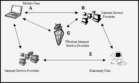
Table 10 Permanently Assigned Multicast Addresses Note that the Multicast Addresses that are used for local routers all have a 02 (0000 0010 binary) in the second highest order byte. The 0 defines the address as permanently assigned. The 2 identifies the scope as Link Local, as would be expected for local routing messages. A router could send router advertisements to the link-local scope Multicast Address to configure or monitor its link-local network. To send a message to all the routers in a given site, the second highest order byte is set to 05. The 5 indicates the site-local scope Multicast Address. This Multicast Address type can be used to quickly update routing information. IPv6 address scalability allows the Multicast Address to be used efficiently and for a variety of purposes. IPv6 RoutingAll of IPv4's routing algorithms are used in IPv6; these include; Open Shortest Path First (OSPF), Routing Information Protocol (RIP), ISO Inter-Domain Routing Protocol (IDRP), and Intermediate System to Intermediate System Protocol (ISIS). Additional routing capabilities have been added to IPv6 through special routing options. Routing options are included in an IPv6 Extension Header called the Routing Header. The Routing Header implements new routing capabilities by creating routing sequences inside of the Extension Header. These routing options may list an intermediate sequence or a path that a packet traverses on its way to a destination. The destination may then easily reverse the address sequence to reach the sender. In this fashion, IPv6 can implement functions like provider selection and extended addresses for mobility. For provide selection the user can dictate a specific path for its packets to take, and request that the destination uses the same path on a reply. For IPv6 address mobility, the destination can use the path to locate the mobile users location. No matter where the mobile user travels, the routing sequence will track the users position. Figure 1.4 illustrates an example of how a mobile user would interact with a destination that can be reached through three different Internet Service Providers. In this illustration, Internet Service Providers A and B provide basic service, as one would connect to from home or office. Internet Service Provider C provides mobile Internet Service for use with mobile internet technology.
Suppose mobile user A was located at their home location and wanted to route a packet to stationary user E. User A could route a packet to user E and select internet provider D to make the connection. The packet from user A would contain the sequence A,D,E. User E would then reverse the sequence to reach user A through the preferred path, the return packet would travel E, D,A. Now, lets suppose user A becomes mobile and travels to a site that is only reachable through wireless internet provider C. Through IPv6 auto-configuration, the mobile user can automatically obtain the proper IPv6 prefix from the wireless provider C. The user would then route a packet to user E in the following sequence; A, C, B, E. User E could then locate the location of user A by simply reversing the sequence. In this fashion, IPv6 routing facilitates address mobility and provider selection. AutoconfigurationThe first step in autoconfiguration is the creation of the Interface Identifier (Interface ID). The Interface ID is usually derived form the IEEE EUI-64 bit format. The IEEE EUI 64 bit address may be derived from the IEEE 48 bit MAC address. When the IEEE 48 bit MAC address is used, the IEEE EUI 64 bit address is defined as global scope. The IEEE EUI 64 is formed by inserting two bytes in the middle of the IEEE 48 bit MAC address, FF FE in hexadecimal. To create the Interface ID from the IEEE EUI 64 format, take the first byte of the new IEEE EUI 64 address and complement the universal/local bit, the second to lowest order bit. In the global scope case this will change the second to lowest order bit from a 0 to a 1. If the IEEE EUI 64 bit address is of local scope, the universal/local bit is set to 0. FE80, as previously described in the Link-Local Address Section, is then pre-appended to the Interface ID to form the Link-Local Address.
Once the Link Local Address is formed, the computer sends an Internet Control Message Protocol for IPv6 (ICMPv6) Neighbor Solicitation with its Link-Local Address to make sure no other computer exists on the local network with the same address. The hosts then waits for a response to indicate if another machine already has that address. If another interface responds with a message indicating that it has already claimed that address, then the interface must be manually configured with a new Interface ID. After a timeout period, if no other host has claimed the address, the node is free to take that Link Local Address to define its interface locally.. IPv6 nodes use Neighbor Discovery protocol to verify addresses as described above. This protocol may also be used to discover or confirm the presence of other nodes, to find routers, or to maintain reach-ability information. The Internet Draft dated February 1998 and titled "Neighbor Discovery for IP Version 6," provides further information on this topic. The computer must also obtain a global IPv6 address. The interface sends out an ICMPv6 Router Solicitation to find the local router. If a router exists on the network, it will respond with a Router Advertisement. The Router Advertisement will include the IPv6 prefix that defines the local network on the internet. This IPv6 prefix is then pre-appended to the Interface Identifier, NOT the Link-Local Address, to make the Global Unicast Address. The process of autoconfiguration is discussed in the Internet Draft dated February 1998 and titled "IPv6 Stateless Address Autoconfiguration." IPv6 over EthernetThe standard Ethernet Frame is used to carry the IPv6 packet. The Ethernet Frame is shown in Table 12.
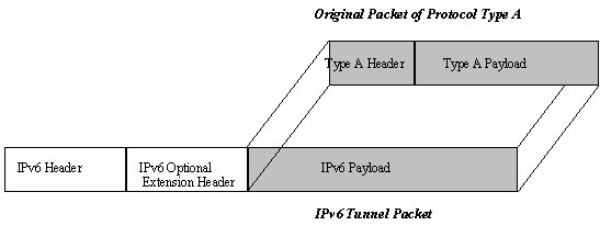
Table 12 Ethernet Frame The Ethernet Header is added to the front of the IPv6 packet to create the Ethernet Frame. The Ethernet Header is similar to the IPv6 Header except that a different address format is used. The 48 bit IEEE MAC address format is used to represent the Recipient and Sender Address Fields in the Ethernet Frame. The Type Field indicates that the contained protocol is IPv6, the Ethernet type code for IPv6 is represented in hexadecimal as 86DD. The Data Field contains the IPv6 headers along with the payload. If the IPv6 packet is too small, padding octets are used in the data field to meet the minimum Ethernet frame size of 46 bits. Zeros are used as padding octets and they are not counted in the calculation of the data field's total length for the IP header. The Preamble and Cyclic Redundancy Check (CRC) fields are used as normally to ensure synchronization and identify errors. The default Maximum Transmission Unit (MTU) for IPv6 over Ethernet is 1500 octets. The MTU size can efficiently be changed across a large network through the use of Router Advertisements. A Router Advertisement is a message that is sent out by a router to all of its on-link nodes for the purpose of providing specific network information. The advertisement would also include the MTU size to be used by all of the nodes unless a node has been manually configured to use a smaller size. Thus, the advertisement of an MTU value that is larger than any interface's manually configured MTU is ignored. The Internet Draft dated November 1997 titled "Transmission of IPv6 Packets over Ethernet Networks," offers more information on this topic. Packet Tunneling in IPv6An Internet Draft dated January 1998 and titled "Generic Packet Tunneling in IPv6," has been specifically written for this topic. The information provided here is simply a summary of the major points covered in this draft. IPv6 provides for the encapsulation of internet packets through IPv6. IPv6 Encapsulation is the process of adding header information before and after a packet in order to pass a packet over a network. This form of tunneling should not be confused with the transition efforts that involve the tunneling of IPv6 packets through an IPv4 network. IPv6 Encapsulation allows different protocols of various types to be carried as the payload of an IPv6 packet. IPv6 supports many different protocol types for encapsulation, these include IPv4, IPX, CLNP and several others. An IPv6 packet that contains an encapsulated protocol is termed an IPv6 Tunnel Packet. The path that the Tunnel Packet traverses from the source of the tunnel to the end of the tunnel is called an IPv6 Tunnel. A packet that is carried over the IPv6 Tunnel may continue in its original protocol packet form once it is de-capsulated at the end of the tunnel. In this fashion, one can take advantage of IPv6 without having to change any of the protocols that are currently in use. Tunneling allows existing protocols to take advantage of IPv6 services such as routing control, Quality of Service, and security. The source or entry point of the IPv6 tunnel encapsulates the original packets and forwards them through the tunnel. The encapsulation process involves pre-appending an IPv6 header and optional IPv6 extension headers to an original packet of protocol type A. Figure 1.14 shows the process of encapsulation. The original packet of type A is processed normally before encapsulation and after de-capsulation. After encapsulation, the IPv6 tunnel packet's header will contain the entry points address as the source and the tunnel exit point as the destination.
The IPv6 Tunnel Packet is processed as any other IPv6 packet along the path through the IPv6 tunnel. IPv6 Extension headers that control the routing path are processed along the route. Other IPv6 Extension headers that are only important to the tunnel endpoint are only processed at the end. At the end of the IPv6 tunnel the IPv6 Tunnel Packet is received and de-capsulated. The de-capsulation process analyzes the Next Header Field to identify the encapsulated protocol of type A. Once the original protocol of type A has been identified, the IPv6 headers are discarded and the original packet is free to continue on to its destination as normal. The Next Header field is the last field processed in IPv6, if this value is not set to a tunnel protocol value, the IPv6 packet is left intact. The original packet may have multiple destinations, thus the tunnel could be used as a point to multi-point connection using IPv6 services. Quality of Service SupportFigure 1.15 illustrates the two IPv6 Header Fields that pertain to Quality of Service (QoS). The Flow Label and the Priority fields in the IPv6 header are used to identify packets that require special handling by routers. QoS, provides a method to guarantee that special types of data flow will have priority over less important types of communication. Certain types of data may be dropped and resent, while other types of data rely on continued throughput. For example, a video-stream would take precedence over a simple internet server request. The priorities may be set by the users according to their preference. 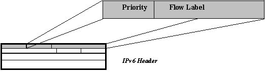 Figure 4 : Quality of Service Format in IPv6 Header The Flow Label option is 24 bits long, it defines a flow that corresponds the type of traffic being transferred. All of the packets for a defined flow type are sent with the same source and destination addresses. The same Flow Label value is used for all of the packets in the same transition. These packets also contain the same values for any Hop-by-Hop or Routing Header Options that may be present in the IPv6 Extension Headers. IPv6 QoS functionality allows the router to define its own QoS values for packets that did not originally contain Flow Label or Priority information. In this case, the router would process all of the IPv6 Headers in the first packet and cache any routing information that it discovered. Any following packets from the same source will then be handled according to the cached information. The router improves efficiency by defining QoS values and avoiding having to process each of the packets singularly. The Priority field is 4 bits long and it enables the source to define a delivery priority for the packet. The priority values are separated into two groups. Values 0 through 7 are used to describe the priority congestion controlled traffic. This type of traffic may be dropped during high congestion periods. The suggested priority values for congestion controlled traffic are shown below:
Values 8 through 15 describe the types of traffic that should not be dropped, such as video-streams and other real-time packets. The lowest priority value is 8, this value is used for packets that the sender is most willing have discarded. A value of 15 indicates the highest priority for packets that the user is most concerned about. Quality of Service operations in IPv6 are still experimental. Interfaces that do not support QoS are required to set the Flow Label field to zero for its outgoing packets and ignore the field on incoming packets. IPv6 Security IssuesIPv6 offers two instruments to provide internet security. The Authentication Header and the Encapsulating Security Header. The Authentication Header is a type of Extension Header that provides security for packets. The Authentication Header contains the calculated results of the authentication algorithm. The algorithms calculation takes the entire packet into account, except for the fields that are usually modified along the transition path. Although, the IPv6 effort suggests the use of keyed MD5 for the authentication algorithm, the extension header is actually algorithm independent. MD5 is proposed to facilitate interoperability in the worldwide internet. Many different algorithms and authentication techniques are supported. It should be noted that the Authentication Header only supports authentication and integrity, not confidentiality. The Encapsulating Security Payload (ESP) Header provides both integrity and confidentiality. Depending on the algorithm used, this header security technique may also provide authentication. This extension header is also algorithm-independent and it is simpler than other similar security protocols. The ESP Header provides confidentiality and integrity by encrypting data and carrying it in the data field of the Extension Header. The user may chose to encrypt either a transport-layer segment (e.g., TCP, UDP, ICMP, IGMP) or the entire IP packet. The full encapsulation of data is necessary to provide confidentiality for the entire packet. The packet contents may be encrypted before the authentication values are calculated, depending on which algorithm is being used. The IPv6 effort suggests the use of the following encryption schemes; Data Encryption Standard (DES), and Cipher Block Chaining (CBC). |
||||||||||||||||||||||||||||||||||||||||||||||||||||||||||||||||||||||||||||||||||||||||||||||||||||||||||||||||||||||||||||||||||||||||||||||||||||||||||||||||||||||||||||||||||||||||||||||||||||||||||||||||||||||||||||